AIR BRAKE SYSTEM OVERHAULS.
Ensuring absolute deceleration integrity in heavy transport.
Fundamentals of Pneumatic Braking
Commercial vehicles operating at 80,000 pounds gross combination weight require braking systems with unparalleled reliability. Hydraulic fluid systems, standard in passenger vehicles, cannot scale to these demands due to the risk of fluid boiling and the physical limitations of hydraulic line routing across articulated trailers. Air brakes provide the necessary kinetic energy dissipation, defaulting to a locked state if system pressure is lost—a critical fail-safe design.
The standard system is comprised of the supply circuit (compressor, governor, air dryers, reservoirs) and the control circuit (treadle valve, relay valves, brake chambers). Complete comprehension of pneumatic logic is required to overhaul these systems safely and effectively.
S-Cam Drum Mechanics vs. Air Disc Brakes
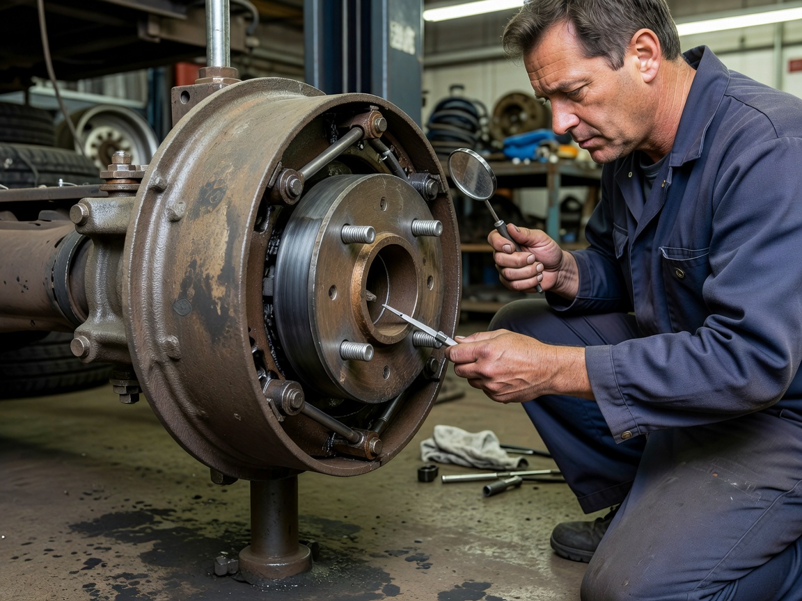
While the industry has seen a gradual shift towards Air Disc Brakes (ADB) due to their resistance to fade and simplified pad replacement, the S-Cam drum brake remains the predominant architecture in the North American fleet market. Overhauling an S-Cam system requires strict measurement protocols.
- Brake Shoe Linings: Federal regulations dictate minimum lining thicknesses. However, proactive fleet maintenance replaces shoes before they reach these minimums to prevent drum scoring and heat-check cracking.
- The S-Cam & Bushings: The splined shaft and S-shaped cam must rotate freely within the spider assembly. Worn cam bushings allow radial play, leading to uneven brake application, chatter, and accelerated lining wear. Radial play exceeding 0.030 inches warrants immediate replacement of the bushings and potentially the cam shaft itself.
- Slack Adjusters: Automatic Slack Adjusters (ASAs) are designed to compensate for lining wear. A common malpractice is manually adjusting ASAs. If an ASA requires manual adjustment, it is inherently failing and must be replaced. Over-greasing can also pack the internal ratcheting mechanism, rendering the ASA useless.
Air Dryer and Compressor Calibration
Moisture is the primary enemy of a pneumatic brake system. Water accumulation in the reservoirs leads to valve corrosion and, critically in cold climates, ice blockages in the control lines. The air dryer desiccant cartridge must be replaced on a stringent schedule—typically annually before winter season.
The governor controls the compressor cut-in and cut-out pressures. Standard calibration sets the cut-out at 120-135 PSI and cut-in no lower than 100 PSI. Technicians must conduct leak-down tests to verify system integrity. A loss of more than 3 PSI per minute (for a tractor-trailer combination) with the brakes applied indicates a critical leak that must be traced via ultrasonic leak detectors or soap solution.
DOT Inspection Parameters
Roadside inspections heavily scrutinize the braking system. Out-of-service (OOS) criteria are strictly enforced. Technicians must understand these parameters to ensure vehicles do not incur violations.
| Component | Defect Condition (OOS Criteria) | Maintenance Action |
|---|---|---|
| Brake Adjustment | Pushrod travel exceeds limit (e.g., 2 inches on Type 30 chamber) | Replace Automatic Slack Adjuster, verify clevis pin geometry. |
| Brake Drums | Cracks extending through the web, or mechanical scoring | Replace drum, inspect shoe lining composition for contamination. |
| Air Lines/Hoses | Audible leak, bulges, or reinforcement ply visible | Replace hose assembly routing away from chafe points. |
Conclusion: Zero-Tolerance Policy
There is no margin for error in heavy-duty brake maintenance. Technicians must approach every valve replacement, hose routing, and foundation brake overhaul with complete adherence to manufacturer service limits. Bypassing a relay valve or ignoring a minor air leak fundamentally compromises the safety of the driver and the public. Structural integrity in braking systems is achieved through measuring twice, replacing worn components proactively, and strictly following pneumatic schematics.